Cara Mudah Membaca Komponen SMD
Komponen Surface Mounting Devices atau yang biasa dikenal dengan komponen SMD merupakan komponen elektronika modern yang diproduksi menggunakan metode Surface Mounting Technology (SMT). Komponen SMD pertama kali dikembangkan pada tahun 1960-an dan mulai digunakan secara massal sejak tahun 1980-an hingga sekarang. Tujuan awal pengembangan komponen SMD yaitu untuk menggantikan teknologi through-hole yang dianggap boros tempat dan kurang efisien. Dengan hadirnya teknologi SMT, produsen dapat memangkas ukuran komponen SMD berkali-kali lipat lebih kecil dibanding komponen through-hole, namun dengan performa yang sama layaknya komponen through-hole.
Gambar 1.0 Komponen SMD
Komponen - komponen elektronika yang mengadopsi tipe mounting SMD umumnya berupa resistor, kapasitor, induktor, IC, transistor, LED, dan beberapa komponen elektronika lainnya. Untuk menginformasikan nilai komponen SMD, produsen menggunakan kode - kode khusus yang biasanya dicetak pada permukaan atas komponen.
Apakah arti dari kode - kode tersebut? Dan bagaimana cara membacanya? Mari kita bahas satu per satu.
Cara Membaca Komponen SMD
1. Resistor
Secara garis besar, pengkodean resistor SMD dibagi menjadi 3 kategori, sistem tiga digit, sistem empat digit, serta sistem EIA-96. Berikut penjelasan dari masing-masing sistem pengkodean tersebut.
- 1.1 Sistem Tiga Digit

Gambar 1.1 Sistem Pengkodean Tiga Digit
Pada sistem ini terdapat 3 digit angka yang berfungsi untuk mendeklarasikan nilai komponen SMD. Angka pertama dan kedua merupakan bilangan numerik yang menunjukan nilai resistansi sedangkan angka ketiga berfungsi sebagai faktor pengali perpangkatan dari bilangan 10. Berikut ini adalah beberapa contoh pembacaan nilai resistansi dari sistem pengkodean 3 digit.
Contoh:
- 101 === 10 Ω x 101 = 100 Ω
- 203 === 20 Ω x 103 = 20.000 Ω / 20 KΩ
- 120 === 12 Ω x 100 = 12 Ω
- 472 === 47 Ω x 102 = 4.700 Ω / 47 KΩ
- 335 === 33 Ω x 105 = 3.300.000 Ω / 3.3 MΩ
Untuk nilai resistansi yang lebih kecil dari 10 Ω biasanya ditulis dengan menambahkan huruf “R”. Huruf “R” mengindikasikan letak poin desimal pada nilai resistansi. Misalnya suatu resistor memiliki kode 4R7, itu berarti resistor ini memiliki nilai resistansi sebesar 4.7 Ω, reistor memiliki kode R05, berarti resistor memiliki nilai resistansi 0.05 Ω, dan seterusnya.
- 1.2 Sistem Empat Digit

Gambar 1.2 Sistem Pengkodean Empat Digit
Sistem ini memiliki mekanisme penghitungan yang sama persis dengan sistem tiga digit, bedanya hanya terletak pada jumlah digit di depan faktor pengali. Berikut ini contoh pembacaan nilai resistansi dengan sistem pengkodean empat digit.
Contoh:
- 1002 === 100 Ω x 102 = 10.000 Ω / 10 KΩ
- 2700 === 270 Ω x 100 = 270 Ω
- 1473 === 147 Ω x 103 = 147.000 Ω / 147 KΩ
- 2204 === 220 Ω x 104 = 2.200.000 Ω / 2.2 MΩ
- 3201 === 320 Ω x 101 = 3.200 Ω / 3.2 KΩ
Sama halnya dengan sistem pengkodean tiga digit, untuk resistor dengan nilai resistansi kecil biasanya disisipi huruf “R”. Misalnya sebuah resistor memiliki kode 3R70, berarti resistor tersebut memiliki nilai resistansi sebesar 3.70 Ω, 0R20 berarti 0.20 Ω, 6R01 berarti 6.01 Ω, dan seterusnya.
- 1.3 Sistem EIA-96
Sistem pengkodean EIA-96 terdiri dari tiga digit kombinasi huruf dan angka. Dua digit angka di depan menunjukkan nilai resistansi sedangkan sebuah huruf di belakang menunjukkan faktor pengali. Pengkodean Jenis ini khusus digunakan untuk menandai resistor dengan nilai toleransi 1%. Berikut cara membacanya.
| Kode | Nilai | Kode | Nilai | Kode | Nilai |
|---|
| 01 | 100Ω | 33 | 215Ω | 65 | 464Ω |
| 02 | 102Ω | 34 | 221Ω | 66 | 475Ω |
| 03 | 105Ω | 35 | 226Ω | 67 | 487Ω |
| 04 | 107Ω | 36 | 232Ω | 68 | 499Ω |
| 05 | 110Ω | 37 | 237Ω | 69 | 511Ω |
| 06 | 113Ω | 38 | 243Ω | 70 | 523Ω |
| 07 | 115Ω | 39 | 249Ω | 71 | 536Ω |
| 08 | 118Ω | 40 | 255Ω | 72 | 549Ω |
| 09 | 121Ω | 41 | 261Ω | 73 | 562Ω |
| 10 | 124Ω | 42 | 267Ω | 74 | 576Ω |
| 11 | 127Ω | 43 | 274Ω | 75 | 590Ω |
| 12 | 130Ω | 44 | 280Ω | 76 | 604Ω |
| 13 | 133Ω | 45 | 287Ω | 77 | 619Ω |
| 14 | 137Ω | 46 | 294Ω | 78 | 634Ω |
| 15 | 140Ω | 47 | 301Ω | 79 | 649Ω |
| 16 | 143Ω | 48 | 309Ω | 80 | 665Ω |
| 17 | 147Ω | 49 | 316Ω | 81 | 681Ω |
| 18 | 150Ω | 50 | 324Ω | 82 | 698Ω |
| 19 | 154Ω | 51 | 332Ω | 83 | 715Ω |
| 20 | 158Ω | 52 | 340Ω | 84 | 732Ω |
| 21 | 162Ω | 53 | 348Ω | 85 | 750Ω |
| 22 | 165Ω | 54 | 357Ω | 86 | 768Ω |
| 23 | 169Ω | 55 | 365Ω | 87 | 787Ω |
| 24 | 174Ω | 56 | 374Ω | 88 | 806Ω |
| 25 | 178Ω | 57 | 383Ω | 89 | 825Ω |
| 26 | 182Ω | 58 | 392Ω | 90 | 845Ω |
| 27 | 187Ω | 59 | 402Ω | 91 | 866Ω |
| 28 | 191Ω | 60 | 412Ω | 92 | 887Ω |
| 29 | 196Ω | 61 | 422Ω | 93 | 909Ω |
| 30 | 200Ω | 62 | 432Ω | 94 | 931Ω |
| 31 | 205Ω | 53 | 442Ω | 95 | 953Ω |
| 32 | 210Ω | 64 | 453Ω | 96 | 976Ω |
Tabel 1 Tabel Nilai Resistansi EIA-96
| Kode | Faktor Pengali | Kode | Faktor Pengali |
|---|
| Z | 0.001 | C | 100 |
| Y/R | 0.01 | D | 10.00 |
| X/S | 0.1 | E | 10.000 |
| A | 1 | F | 100.000 |
| B/H | 10 | | |
Tabel 2 Tabel Faktor Pengali EIA-96
Contoh:
- 09A === 121 Ω x 1 = 121 Ω ± 1%
- 78C === 634 Ω x 100 = 63.400 Ω / 63.4 KΩ ± 1%
- 40Y === 255 Ω x 0.01 = 2.55 Ω ± 1%
- 17A === 147 Ω x 1 = 147 Ω ± 1%
- 30Z === 200 Ω x 0.001 = 0.2 Ω ± 1%
2. Kapasitor Keramik
Gambar 2.0 Sistem Pengkodean Empat Digit
Sebagian besar kapasitor keramik SMD yang beredar di pasaran umumnya tidak dilengkapi kode tercetak untuk menandakan nilai kapasitansinya. Namun terkadang ada beberapa produsen yang menyertakan kode tersebut pada permukaan atas komponen. Jika Anda menemukan kode tersebut, berikut cara membacanya.
| Kode | Nilai (pF) | Kode | Nilai (pF) | Kode | Nilai (pF) |
|---|
| A | 1.0 | M | 3.0 | Y | 8.2 |
| B | 1.1 | N | 3.3 | Z | 9.1 |
| C | 1.2 | P | 3.6 | a | 2.5 |
| D | 1.3 | Q | 3.9 | b | 3.5 |
| E | 1.5 | R | 4.3 | d | 4.0 |
| F | 1.6 | S | 4.7 | e | 4.5 |
| G | 1.8 | T | 5.1 | f | 5.0 |
| H | 2.0 | U | 5.6 | m | 6.0 |
| J | 2.2 | V | 6.2 | n | 7.0 |
| K | 2.4 | W | 6.8 | t | 8.0 |
| L | 2.7 | X | 7.5 | y | 9.0 |
Tabel 3 Kode Nilai Kapasitansi Kapasitor SMD
Contoh:
- E4 === 1.5 pF x 104 = 15.000 pF / 15 nF
- S2 === 4.7 pF x 102 = 470 pF
- R5 === 4.3 pF x 105 = 430.000 pF / 430 nF
- KG3 === 1.8 pF x 103 = 1.800 pF / 1.8 nF (diproduksi oleh pabrik berinisial “K”)
- AT1 === 5.1 pF x 101 = 51 pF (diproduksi oleh pabrik berinisial “A”)
3. Kapasitor Elektrolit
Gambar 3.0 Pengkodean Kapasitor Elektrolit
Secara umum nilai kapasitansi dari suatu kapasitor elektrolit dicetak dengan menggunakan kombinasi satu digit huruf dan tiga digit angka. Berikut cara membaca nilai kapasitansi dari kapasitor SMD.
| Kode | Tegangan | Kode | Tegangan |
|---|
| e | 2.5 V | D | 20 V |
| G | 4 V | E | 25 V |
| J | 6.3 V | V | 35V |
| A | 10 V | H | 50 V |
| C | 16 V | | |
Tabel 4 Tabel Kode Tegangan Kapasitor Elektrolit
Contoh:
- E572 === 57 pF x 102 = 5.700 pF / 5.7 nF @ 25 V
- C475 === 47 pF x 105 = 4.700.000 pF / 4.7 µF @ 16 V
- H103 === 10 pF x 103 = 10.000 pF / 10 nF @ 50 V
- A204 === 20 pF x 104 = 200.000 pF / 200 nF
- D211 === 21 pF x 101 = 210 pF
4. Induktor
Untuk menandakan nilai induktansi, produsen biasanya mencetak tiga digit kode khusus pada permukaan atas induktor SMD. Berikut ini cara membaca kode pada induktor SMD.
Gambar 4.0 Pengkodean Induktor SMD
Contoh:
- 101 ===10 µH x 101 = 100 µH
- 465 === 46 µH x 105 = 4.600.000 µH / 4.6 H
- 273 === 27 µH x 106 = 27.000 µH / 27 mH
- 3R3 === 3.3 µH (huruf “R” menunjukkan letak poin desimal)
- 4R7 === 4.7 µH (huruf “R” menunjukkan letak poin desimal)
Nah.. Bagaimana teman-teman? Membaca nilai komponen SMD ternyata bukan suatu hal yang sulit bukan??
Jangan bosan-bosan belajar elektronika ya.. ^_^
Sampai jumpa di artikel berikutnya..


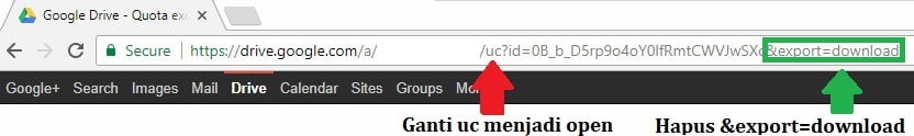
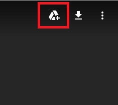
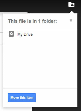
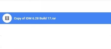
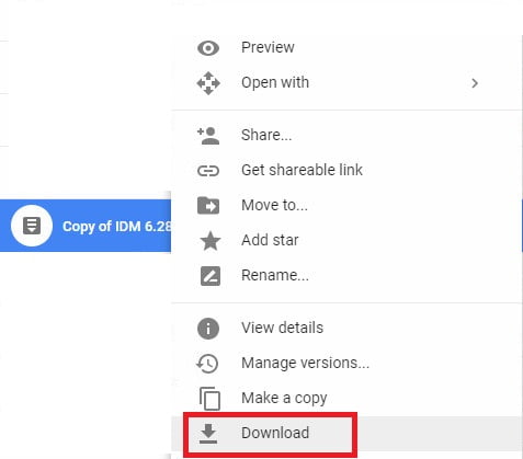
 Google drive adalah salah satu platform yang populer untuk menyimpan dan membagikan file karena penggunaannya yang mudah dan tentunya kecepatan download yang maksimal. Namun, terkadang kita mengalami limit download khususnya pada file yang di download oleh banyak orang sehingga kita harus menunggu 24 jam untuk dapat mendownload file tersebut. Hal tersebut dapat kita atasi dengan membuat salinan pada drive yang kita punya kemudian kita download. Prosesnya pun tergolong mudah dan tidak terlalu sulit untuk diikuti. Penasaran caranya?
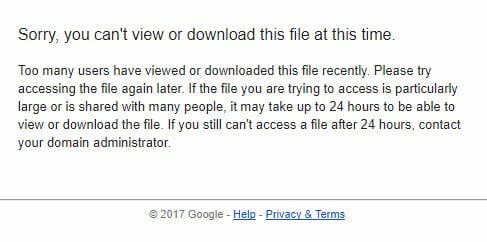

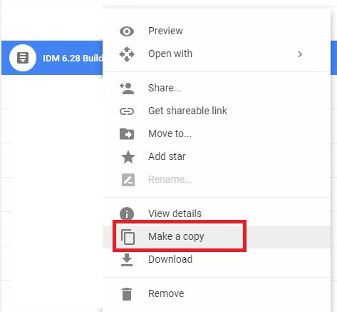


 Print this page